

Wrote by Naoufal E., Cloud Expert
Making serverless architectures tied to microservices architectures on the AWS Cloud is a fun job, and it allows us to learn new things every day !
But mostly, we need Abstract Patterns that already exist to implement and adapt them according to our use case to avoid spending a lot of time designing something that already exists.
My goal here is to introduce you to one of my favorite Patterns that securely tie serverless and micro-services architecture.
This Pattern will help you to save lots of time when designing and thinking about a project that requires authentication to access one or more microservices deployed in a private network.
It is Strong, Secure, Serverless, and Micro, So I named it S3M, and I’m going to make it as Abstract as possible, and implement it with a concrete example of my favorite trending technologies, so you’ll have the choice to implement it your way 💪.
The Use Case
Assuming that we are invited to develop an application that consists of a Front-end that communicates with many microservices backends that are deployed on containers managed by ECS/Fargate (or EKS) and protected in a private network.
All those microservices will use the same logic of authentication / authorization. For example: blocking all non-authenticated calls, verifying the JWT token, and requesting roles from a DynamoDB table to manage permission.
A custom Authorizer as a solution is the best choice to centralize all auth logic rather than developing each logical authentication/authorization for each micro-service, but how? 👌
To access those micro-services, we need to implement the API Gateway private integration: all requests will be verified by the authorizer of the API Gateway and passed through an NLB in a private network by a VPC Links that routes incoming requests (API calls) to the targeted resource (Containers). Take a look at the architecture below.
Project Architecture
To understand S3M Abstract Pattern with a concrete example, we’ll follow this architecture :
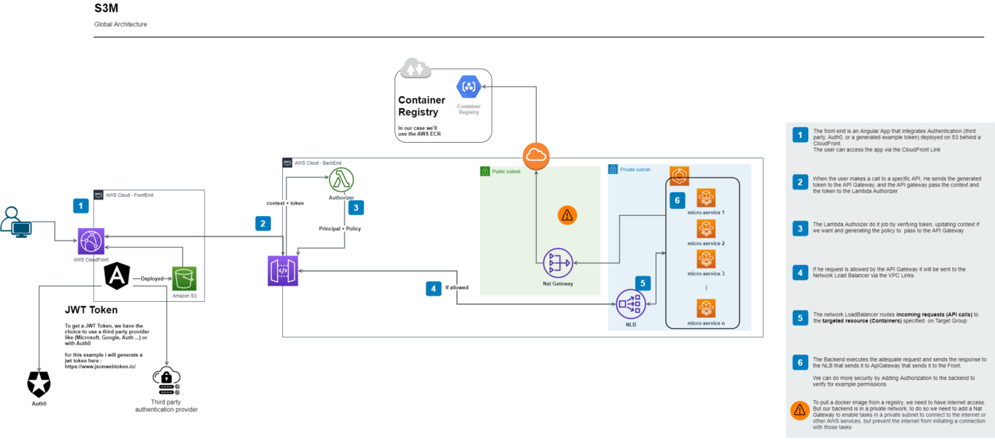
Resume: We have a front that communicates with a backend having as entry point an API Gateway that includes Authorizer In Front of private NLB that routes incoming requests to the targeted resource (Containers)
So, as you can see, the S3M Pattern consists of a(n):
- Authentication Provider to generate a JWT Token (I’ll make it simple 😊, so I’ll generate one here)
- Front-end framework (Angular in my case)
- Backend-end API (.Net Core in my case)
- Private and Public Subnets
- Container Manager and Containers for backend deployment (ECS/Fargate in my case)
- Registry for docker image (ECR in my case)
- NLB (Network Load Balancer)
- VPC Links
- API Gateway
- Lambda Authorizer (NodeJs in my case)
Take a deep breath and analyze the architecture to fully understand it, and if all seems good, it’s time to get our hands dirty 😊
Prerequisite:
→ AWS Account
→ AWS Programatically Acount with Programmatic access and Admin Permission
→ Basic knowledge of the backend and frontend technos besides an initiation in the AWS cloud will be better to completely understand
Here below, I will show you the implementation by using AWS Console.
Steps for Technical Implementation
Step 1: let's create our Angular Front-End :
Prerequisite:
→ Install Angular Globally in your machine, open a terminal and type
npm install -g @angular/cli
- Clone the Angular project example from my GitHub Repo or you can follow the steps bellow
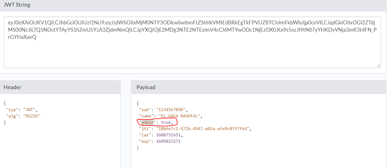
- Generate your JWT Token here and replace it at the
app.component.ts
import { Component } from '@angular/core';
import { HttpClient, HttpParams } from '@angular/common/http';
import { environment } from 'src/environments/environment';
import { Observable } from 'rxjs';
const token =
  'eyJ0eXAiOiJKV1QiLCJhbGciOiJIUzI1NiJ9.eyJzdWIiOiIxMjM0NTY3ODkwIiwibmFtZSI6IkVMIEdBRkEgTkFPVUZBTCIsImFkbWluIjp0cnVlLCJqdGkiOiIxOGI2ZTdjMS00NzJiLTQ5NDctYTAyYS1hZmU5YzA3ZjdmNmQiLCJpYXQiOjE2MDg3NTE2NTEsImV4cCI6MTYwODc1NjEzOX0.Kx9s5ozJl9tN87yYHKDyVNja3mK3t4FN_PrGYHaXavQ';

@Component({
  selector: 'app-root',
  templateUrl: './app.component.html',
  styleUrls: ['./app.component.scss'],
})
export class AppComponent {
  title = 's3a-example';
  items: Observable<any[]>;
  /**
   *
   */
  constructor(private httpclient: HttpClient) {}

  // The best practice is to define a service that call backend api
  // And to make an interceptor that add the generated token to the request header
  // But for saving time, in this tuto i will make him here because is not a tuto about Angular
  getAll() {
    // Generate token example
    console.log('token');
    this.items = this.httpclient
      .get<any[]>(`${environment.baseURL}WeatherForecast`, {
        headers: { Authorization: `Bearer ${token}` },
      })
      .pipe();
  }
}
Step 2: let's create our backend with .net core :
Prerequisite:
→ Install Visual Studio 2019 or VSCode with .netcore
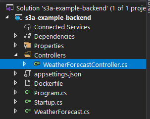
- Clone the .net core project from my GitHub Repo
- You will find this example controller (WeatherForecastController with GET method): it sufficient for our test
I already enabled cors, then we can access the backend from any origin globally.
app.UseCors("AllowOrigin");
services.AddCors(c =>
  {
  c.AddPolicy("AllowOrigin",
    options => AllowAnyOrigin().AllowAnyHeader().AllowAnyMethod());
  });
Step 3: let's make a local test :
- Start your Backend by clicking on the play button of your Visual Studio and copy-paste the localhost port of your backend in the dev environment variable (environement.ts) of your Angular front (in my case the backend port is 49159)
export const environment = {
  production: false,
  baseURL: 'http://localhost:49159/', // replace it by the url of your backend
};
Start your angular project → in the route folder of your cloned front-end, open a terminal, and type:
npm i // to install all dependency
ng serve
- The interest of this test is to see if the back and the front communicate without any problem locally, as well as to be sure that the JWT Token has been passed in the header of the request.
Step 4: prepare our AWS infrastructure
1. Create a container in ECR (Elastic Container Repository):
Amazon Elastic Container Registry (ECR) is a fully managed container registry that makes it easy to store, manage, share, and deploy your container images and artifacts anywhere.
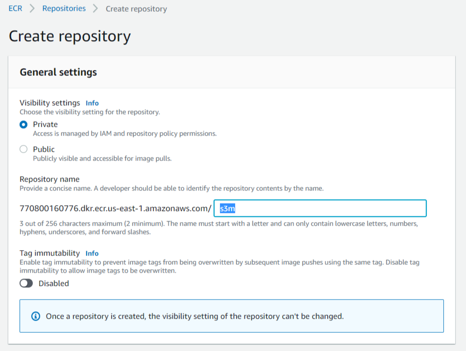
- Open the ECR Dashboard
- Click on “Create Repository”
- Name your repo and click “Create Repository”, that’s it! 😜
2. Create an ECS Cluster (Elastic Container Service):
Amazon ECS makes it easy to deploy, manage, and scale Docker containers running applications, services, and batch processes. Amazon ECS places containers across your cluster based on your resource needs and is integrated with familiar features like Elastic Load Balancing, EC2 security groups, EBS volumes, and IAM roles.
- After creating the repo you will stay on the same page in which you can create also a cluster or you can go here
- Click on the Clusters at the left menu and click on “Create Cluster”
- Select the template Networking Only and click “next step”
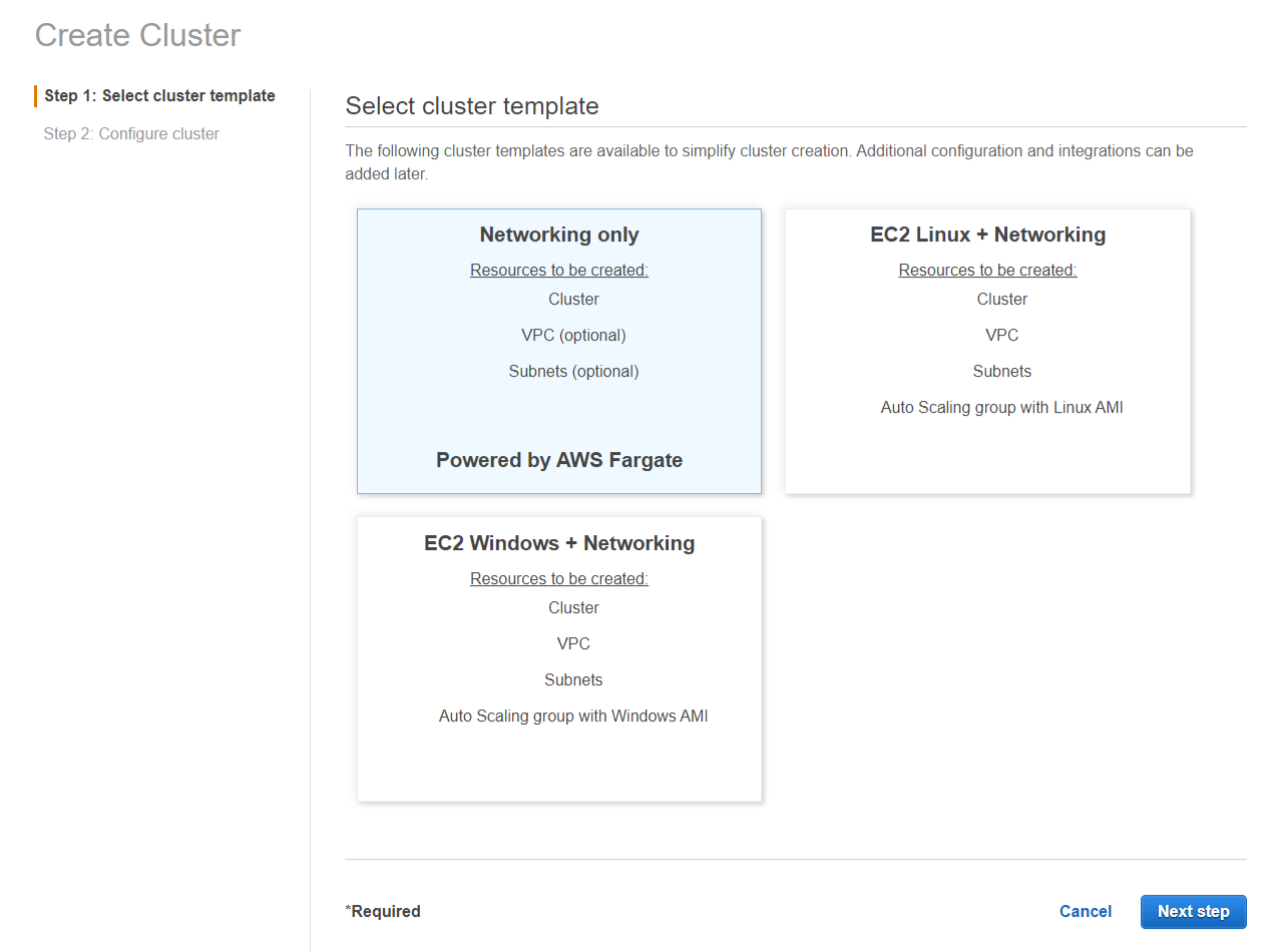
- Name your container and check the “Create VPC” option, choose 3 subnets and click “Create” and wait.
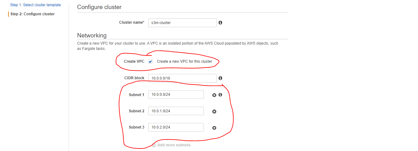
- y default, the created subnets are public so, in the next step, we will make two of them privates and create a NatGateway in the public one to allow private resourceslike ECS Tasks to pull docker images from the registry.
3. Configure VPC :
A VPC is an isolated portion of the AWS cloud populated by AWS objects, in the step before we create one with 3 public Subnet
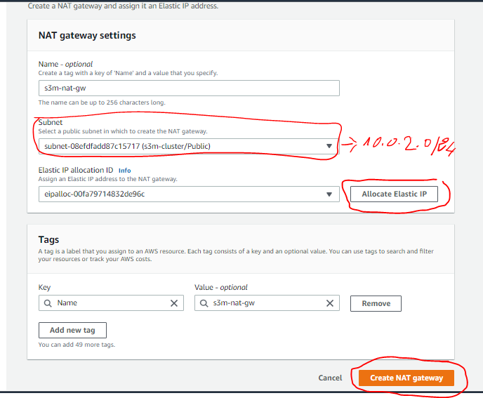
Let's make 2 of them private and leave one Public (for example the 10.0.2.0/24 will stay public)
- Go to VPC Dashboard and create a new NatGateway and as a subnet choose the one that you’ll let it public (I choose 10.0.2.0/24 )
- ⚠️ to know the IP of the subnet go to the subnets table
Go now to the “Route Table”, you will notice 2 new ones are created, one private and one public, and the public one has the three created subnet.
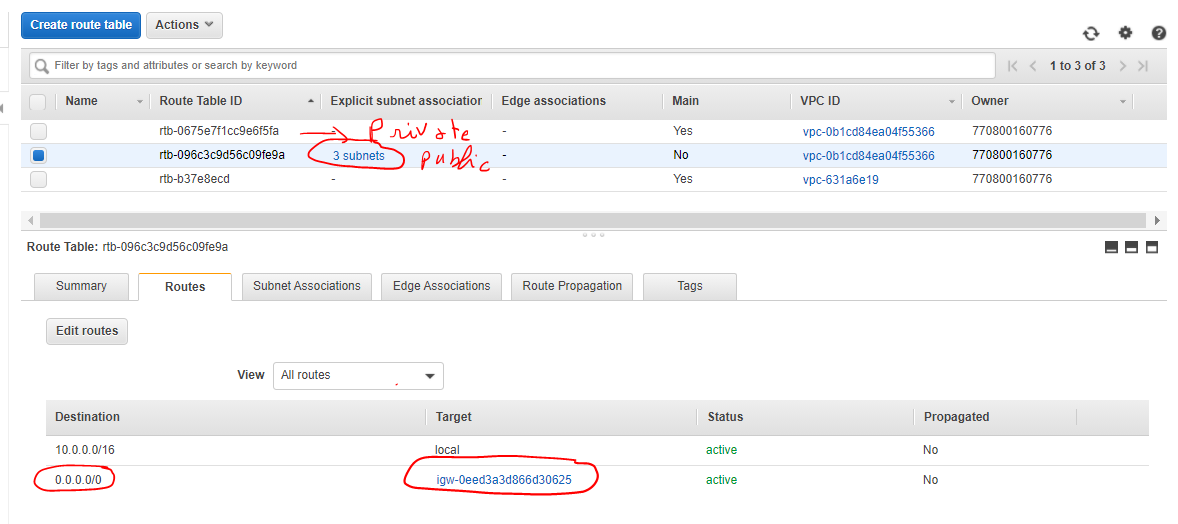
Select the private route table → in the route tab click on “edit route” and add a route to the Nat Gateway created.
0.0.0.0/0 => NatGateway
- Now associate the remaining subnets (2 Subnets) to this route table (private) and change their names (replace /public by /private) → In the “Subnet Associations” tab click on “Edit Subnet Association” and select the subnets to associate (10.0.0.0/24 and 10.0.1.0/24).
Done for the container and the subnets, we will back again to create services and tasks … don’t worry ! These steps is for preparing infrastructures
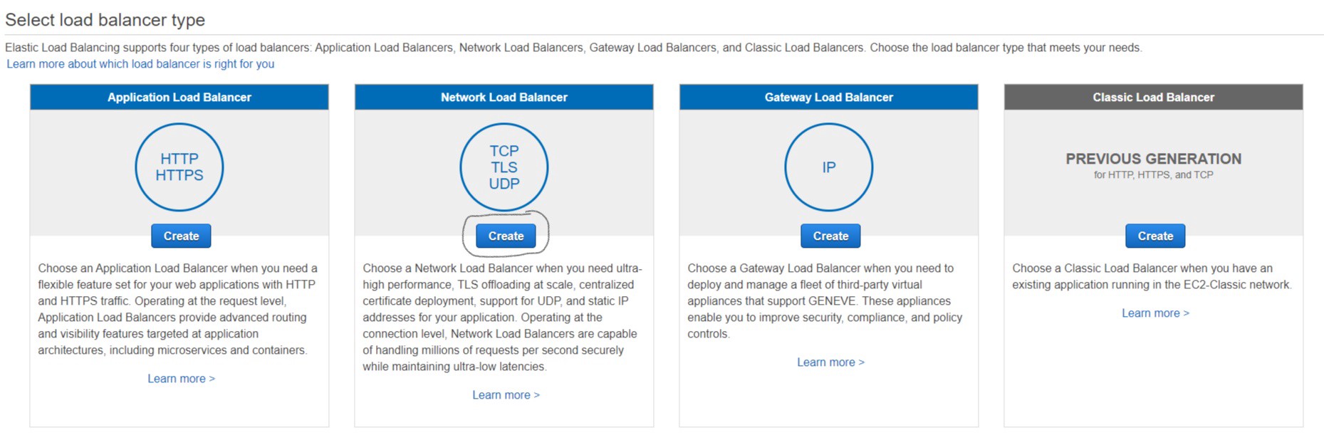
4. Create an NLB :
Elastic Load Balancing automatically distributes your incoming traffic across multiple targets, such as EC2 instances, containers, and IP addresses, in one or more Availability Zones.
Network Load Balancer functions at the fourth layer of the Open Systems Interconnection (OSI) model. It can handle millions of requests per second. After the load balancer receives a connection request, it selects a target from the target group for the default rule. It attempts to open a TCP connection to the selected target on the port specified in the listener configuration.
- Go to EC2 console in the left menu scroll down, click on “Load Balancers” then on “Create Load Balancer” then choose “Network Load Balancer” and click “Create”
Name your NLB, The schememust be “internal” and for VPC. So, you should select the “created one (Step 4.3) ” and check all its private subnets.
- Click “Next: Configure Security Settings” then “Next: Configure Routing”
- For Target Type choose IP → for Protocol choose “TCP” → then “Next: Register targets” then “Next: Review” and “Create”
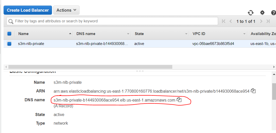
- Copy the DNS Name of the created NLB, we'll need it for the VPC Links
Don’t worry, we will register our target after creating our cluster’s service 😜
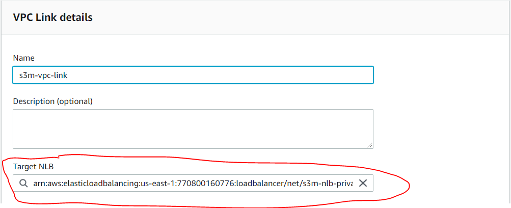
. Create the VPC Link :
VPC link is encapsulated by an API Gateway resource of VpcLink. It is responsible for forwarding API method requests to the VPC resources and returns backend responses to the caller. For an API developer, a VPCLink is functionally equivalent to an integration endpoint.
- Go to the API Gateway dashboard, in the left menu click “VPC Links”, then click “Create” and choose “VPC Link for REST APIs”
- Name it, and for “Target NLB”, you know what to do 😝 (select the NLB created in the step before(Step 4.4) and click “Create”
⚠️ The VPC Link takes a few minutes for creation, so is recommended to wait for its creation before going to the next step.
6. Create the ApiGateway and connect it to the NLB:
API Gateway API with private integration provides our customers access to HTTP/HTTPS resources within your Amazon Virtual Private Cloud (Amazon VPC). Such VPC resources are HTTP/HTTPS endpoints on an EC2 instance behind a Network Load Balancer in the VPC. The Network Load Balancer encapsulates the VPC resource and routes incoming requests to the targeted resource.
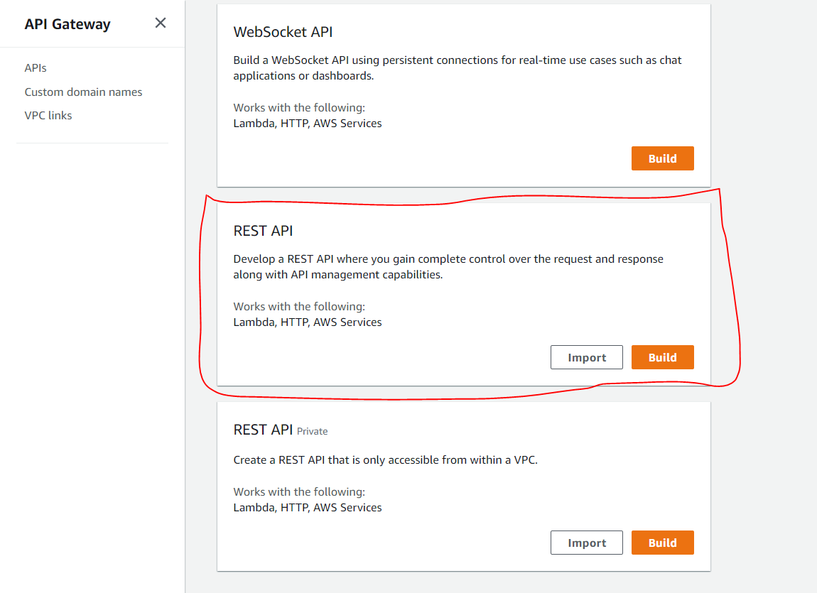
- Go to the API gateway Dashboard and click “Create API”, choose the “REST API” Template and click “Build”.
- Select “New API” then name it and click “Create API”
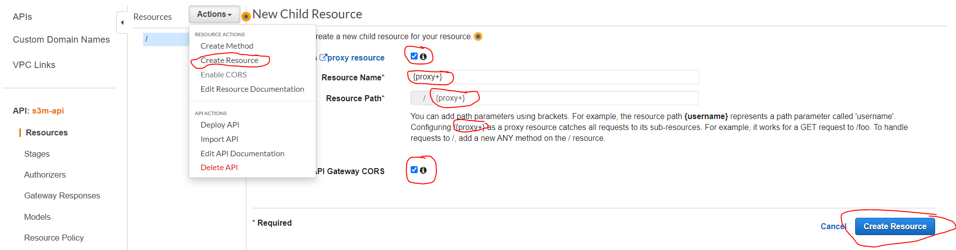
- Click “Action/Create Resource then configure as explained in the image below and click “Create Resources”
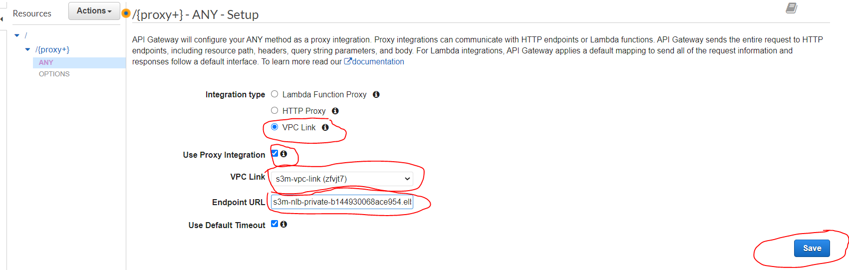
- By default the method “Any” is created in this resource and we should just configure it by selecting the “VPC link” and copy-paste the generated “DNS of the NLB” that we have created before (Step 4.4) concatenated by “/{proxy}” at the endin the endpoint URL as explained in the image below, then click “save”.
- For example, if your DNS is: s3m-nlb-private-b144930068ace954.elb.us-east-1.amazonaws.com in the endpoint URL should be: http://s3m-nlb-private-b144930068ace954.elb.us-east-1.amazonaws.com/{proxy}
So, as you can see, we created our Container Manager (ECS Cluster), our container registry (ECR), and also our NLB connected with API Gateway via the VPC Link.
Almost done, you can take a 15 min break ✌️. The next step will be to connect the Lambda Authorize with the API Gateway.
7. Create the Lambda Authoriser:
A Lambda authorizer (formerly known as a custom authorizer) is an API Gateway feature that uses a Lambda function to control access to your API.
A Lambda authorizer is useful if you want to implement a custom authorization scheme that uses a bearer token authentication strategy such as OAuth or SAML, or that uses request parameters to determine the caller’s identity.
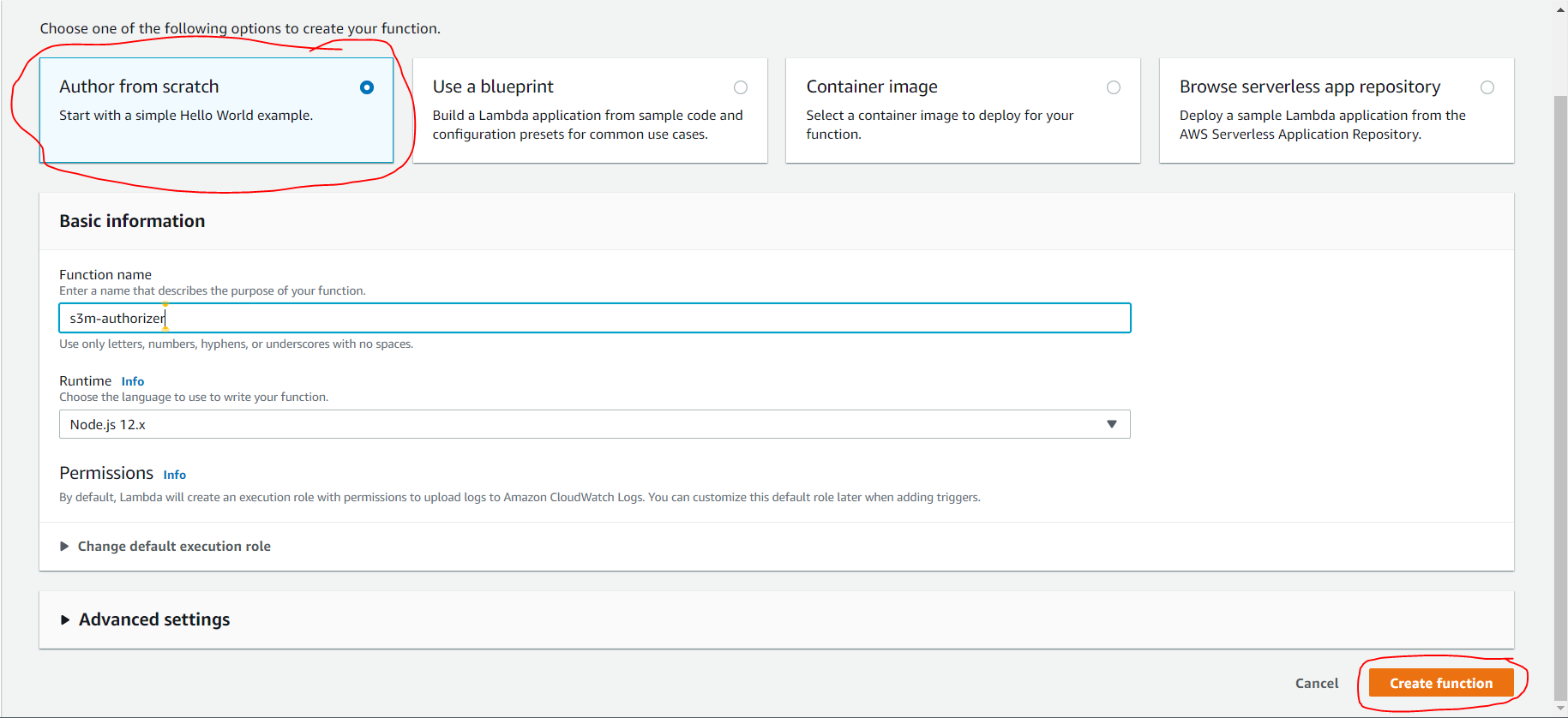
- Go to Lambda dashboard and click on “Create Function”, Select “Author From Scratch”, name it, leave the runtime at node.js 12.x, then click “Create Function”
- You can download the lambda zip from my Github Repo
- Scroll down to Function code, on the right side click on “Actions” and upload “Upload a .zip file”, then upload the downloaded zip and click “save” (I made this zip for you to avoid creating “layers” etc …)
This gist is inspired by AWS Labs
8. Attach the Authoriser to the API Gateway:
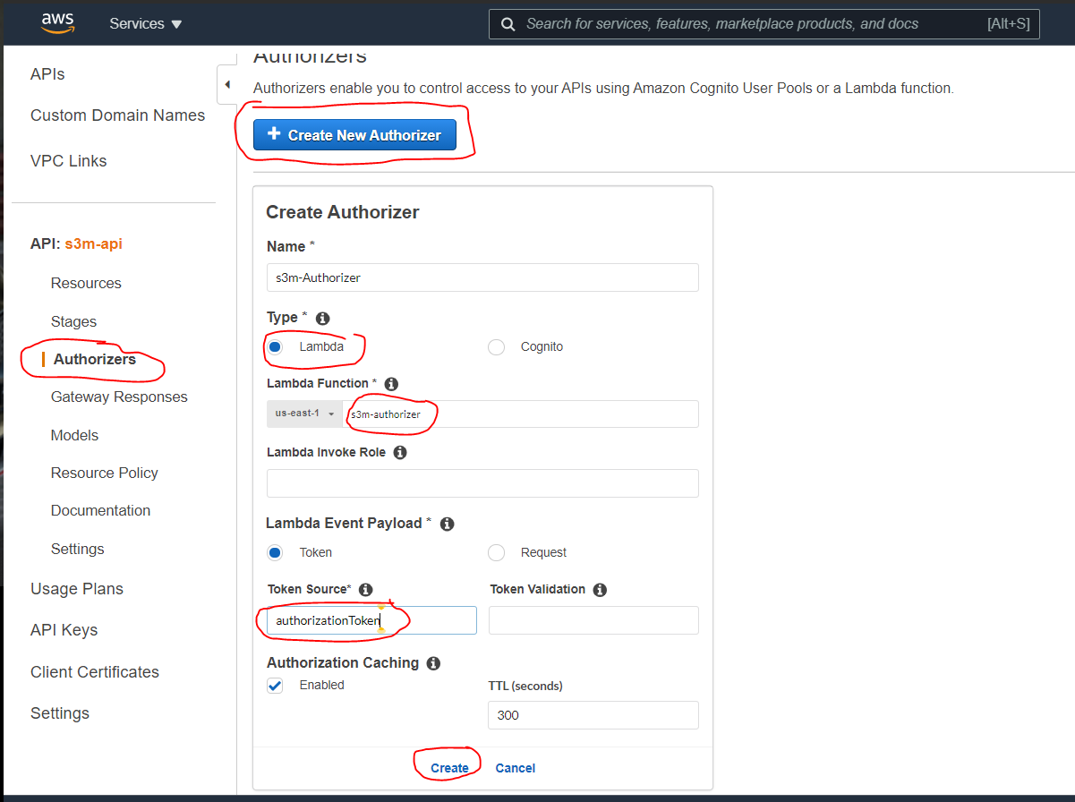
- Go to ApiGateway Dashboard (always verify your region) and select the API that you created before (Step 4.5), in the left menu scroll down to the Authorizers and click on “Create new Authorizer” → name it → at the Lambda Function select the one we have created before (Step 4.7), for “Lambda Event” check “Token” and copy-paste “Authorization” in Token Source, then click on “Create” and “Grant & Create”
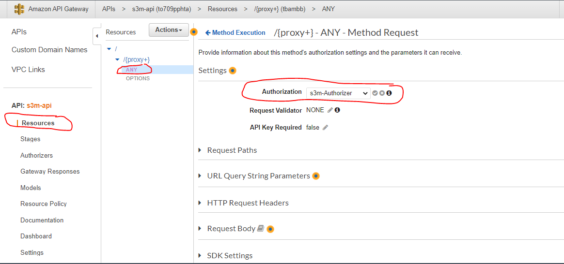
- Now attach the Authorizer to the resources → Select “Resources” in the left menu → select “Any” method and click on “Method Request” → then attach the created Authorizer (if the authorizer doesn't appear refresh the page)
- Now let deploy our API Gateway (choose a new stage and create one) and copy-paste the API Endpoint into the Angular project Prod environment variable (environment.prod.ts) that you have cloned before (Step 3.1). !!! (make sure to have “/” at the end of the endpoint)
→ Next Step we’ll prepare S3 Bucket for hosting our front
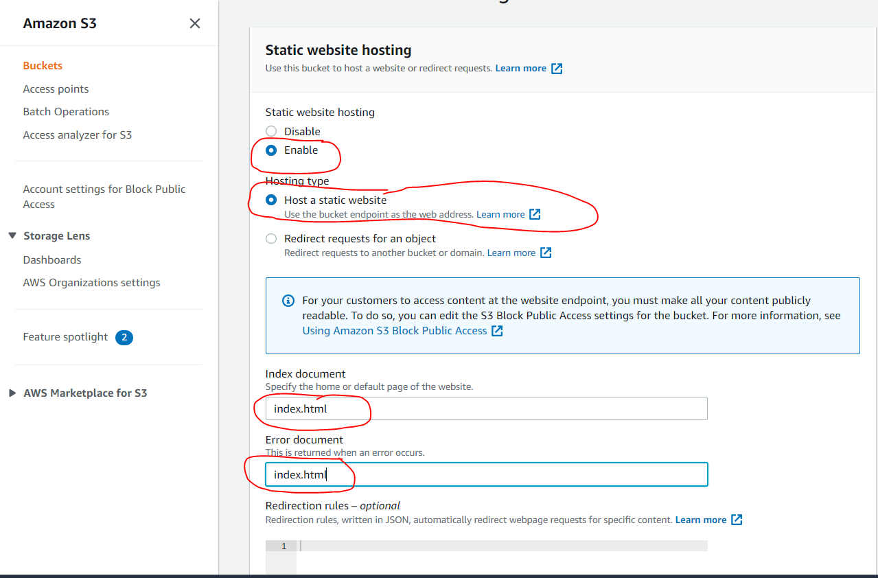
9. Create S3 Bucket for Static Web Site Hosting:
You can use Amazon S3 to host a static website. On a static website, individual webpages include static content. They might also contain client-side scripts.
- Go to S3 Dashboard and click on “Create bucket”, name it, uncheck “Block all public access” then check “I Acknowledge….”, then click “Create Bucket”

- Now enable “Static Web Site Hosting”, to do so → select the created Bucket → to go to “Properties” → Scroll down to the bottom, at Static website hosting click on “Edit” → then enable it as shown in the image below → then click “Save changes”
Our Infrastructure is Ready now, let deploy our front, back, create task and services and bring all pieces together 💪
Step 5: Bring All Pieces together (Deployment):
Let host our Angular Front-end :
- In the route directory of the Angular Project, open a terminal and type
ng build --prod
- It will generate a new folder called “dist”
- Open the S3 Dashboard → select the bucket that we created before (Step 4.9) and click on “Upload” → then go to the generated “dist” folder and drag and drop all its contents to this Bucket.
- All the contents should be reachable by everyone, take a look at the GIF below
- Check the link of your hosted application (properties of the bucket scroll down to Static Web Hosting)
Let's deploy our backend as a Docker image :
Prerequisite:
→ Install the latest version of the AWS CLI
- Go to ECR Dashboard (always verify region) and select the repository that we created before (Step 4.1)
- Click on “View Push Command” to see the command that should be used to push the docker image
- Go to the “route folder” of your backend solution and open a terminal
- Follow the “View push Command” window, then replace the second command with this one
docker build -t s3m-test -f .\S3MExampleBackend\Dockerfile .
- Copy the URI of the pushed image
Let's create a Task Definition
Task definitions specify the container information for your application, such as how many containers are part of your task, what resources they will use, how they are linked together, and which host ports they will use.
- Go to ECS Dashboard, in the left menu select “Task Definitions” then click on “Create New Task Definition”
- Select Launch Type as Fargate
- Name your task → scroll down to Task Execution Role, if you haven't yet a role select “create one” it will be created automatically.
- Add your container (name it → past the URI of pushed image → For memory Limits take 128, and for port-mapping take 80
Let Create a Service :
A service lets you specify how many copies of your task definition to run and maintain in a cluster. We will use it with a Network Load Balancer to distribute incoming traffic to containers in our service.
- Go to the ECS Dashboard → in the left menu select “Clusters” then select the Cluster that we created before (Step 4.2)
- In the “Service tab” click on “Create”
- For Launch Type select “Fargate” → for Task Definition select “the one created before (Step 5.3) ” → give it a name and a number of tasks → then click “Next Step”
- For the VPC choose the “created VPC” (Step 4.3) and select its private network
- For Load Balancer select the “One Created Before” (Step 4.4) and for production listener, select TCP:80 → then click on “next step” then “Create Service” → then “view Service” and wait for task Status to become “RUNNING”
All pieces now are together let test our application
Test the Applications
- Search the link of your hosted app in s3 (Step 5.1 scroll down to static Web Hosting and open the link)
- Example: http://s3m-angular-front.s3-website-us-east-1.amazonaws.com
- Click on the button “Get weather” and you will see your app working

Yeeeeeeees everything work like a magic 😜
That means, all pieces are well connected and we respect every step of the infrastructure as well as deployment to make our project works.
Also, in the Authorizer code, we tell it that only admin can make a call, and in the generated token if you remember admin is set to true
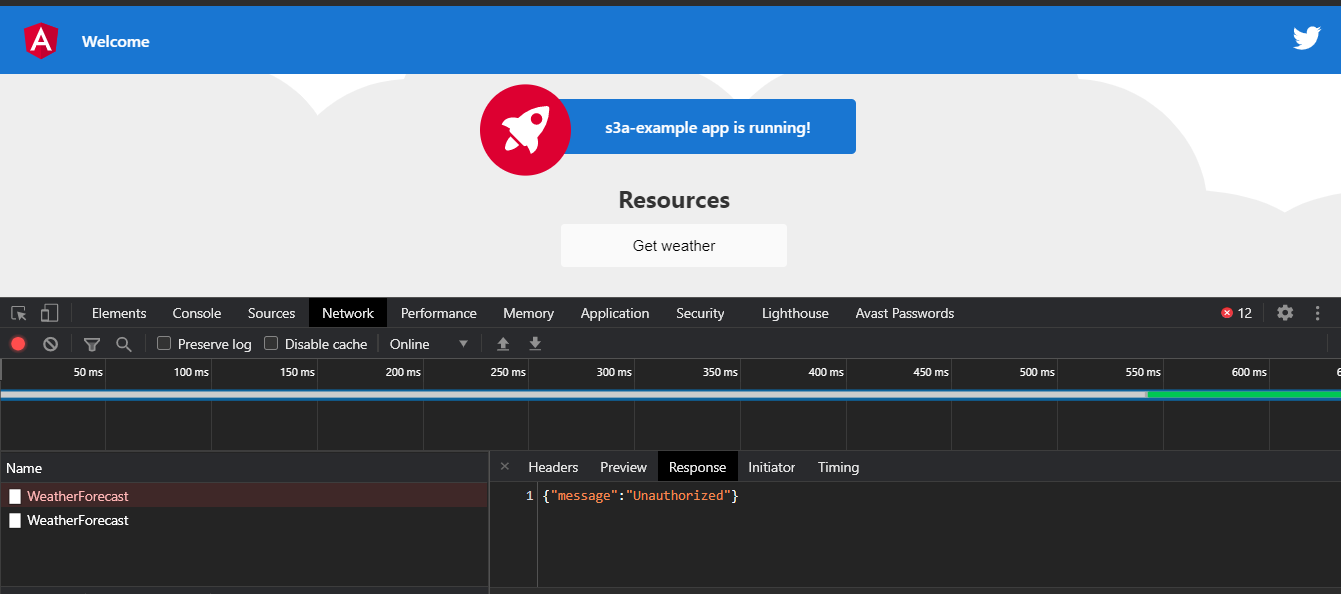
Let reverse the if’s condition of the Lambda Authorizer and see what happen, so if the user is not admin he can do a call otherwise no
- Go to Lambda Dashboard → Select the one created before (Step 4.7) → scroll down to the code and replace
if(decodedJwt.admin) by if(!decodedJwt.admin)
- Then Deploy the function → you will see that you are not authorized to make this call
Conclusion
My goal here is to make it easy for everyone to implement the S3M Pattern.